
These instructions describe how to change the cam belt on S1 cars with a Rover K series engine.
NOTE: ANY WORK THAT YOU PERFORM ON YOUR OWN OR SOMEONE ELSE'S CAR IS ENTIRELY YOUR OWN RESPONSIBILITY. PLEASE DO NOT ATTEMPT THIS WORK IF YOU ARE NOT CONFIDENT YOU CAN COMPLETE IT SAFELY. ALWAYS FOLLOW GOOD WORKING PRACTICES AND NEVER TAKE RISKS OR SHORT CUTS. WHILST EVERY EFFORT HAS BEEN MADE TO ENSURE THAT THESE INSTRUCTIONS ARE COMPLETE THEY SHOULD ONLY BE CONSIDERED A GUIDE - NO GUARANTEE IS MADE THAT THEY ARE COMPLETE OR EXHAUSTIVE.
PLEASE READ THESE INSTRUCTIONS THROUGH COMPLETELY AND THOROUGHLY BEFORE STARTING THE WORK. IF YOU ARE IN ANY DOUBT OR HAVE ANY QUESTIONS PLEASE CONTACT US AT instructions@tadts.com.
If you have any comments/suggestions or notice any errors/omissions please let us know at instructions@tadts.com.
General working recommendations
When removing parts from a car it is always a good idea to place them in a container rather than leaving
them on the floor. This reduces the risk of damaging them by treading on them and also keeps them cleaner
and easier to move around. Something like an old metal tray or biscuit tin is ideal - large enough to hold
most parts, strong enough to take the weight and robust enough to last.
Be methodical about the work and wherever possible work on a small part of the car at a time. This will help you be able to remember what you have done so that reassembly is easier.
Try and be tidy as you work - put tools back on a bench/in a box as they can be dangerous left lying around on the floor and are more difficult to find.
Please read these instructions through thoroughly before starting the work. If you have any questions/comments please feel free to contact us at the email address given at the top of the page.
Estimated time required: 7 hours 50 minutes
Please note that this estimated time is a rough guide and is based on a relatively inexperienced person
performing the task for the first time. It should cover most 'worst-case' scenarios and you will
probably find you complete the task in much less time.
Tools required
| - 13mm open-ended spanner | - 10mm ring spanner |
| - Large cross-headed screwdriver | - Blunt flat-bladed screwdriver |
| - Small mole grips | - Permament pen |
| - Suitable jack and protective pad (e.g. a piece of wood) | - Two chocks (e.g. house bricks) |
| - Four ramps | - Axle stands and suitable protection (2) |
| - Support for front of car (e.g. full boxes of paper, axle stands and suitable protection) (2) | - Cross-headed screwdriver |
| - Small screwdriver flat-bladed screwdriver | - Pliers |
| - Wire cutters | - Large flat-bladed screwdriver |
| - Camshaft pulley locking tool | - Wire brush |
| - 10mm spark plug socket | - Socket handle and extension bars |
| - 8mm socket | - 13mm socket |
| - 6mm allen key bit | - 19mm socket |
| - Road wheel bolt special tool (S2 only - supplied with car) | - 17mm socket |
| - Road wheel locking nut/bolt key (supplied with car) | - Breaker bar |
| - 10mm socket | - 15mm socket |
| - 22mm socket (short) | - 8mm allen key bit |
| - 18mm socket | - Torque wrench |
Materials required
| - Cable ties | - New manual cam belt tensioner |
| - Rag/cloth/tissue | - New cam belt |
| - Permabond | - New alternator drivebelt (K series) |
| - Oil (for spark plug threads) | - Copper grease |
Torque settings
| - Manual cam belt tensioner main bolt (K series) 45Nm | |
| - Manual cam belt tensioner adjustment bolt (K series) 10Nm | - Timing belt lower cover bolt (K series) 9Nm |
| - Crankshaft pulley bolt (K series) 205Nm | - Right-hand engine mount bolt (K series) 82Nm |
| - Alternator pivot and clamp bolts 30Nm | - Spark plug (K series) 25Nm |
| - Timing belt upper front cover bolt (K series) 5Nm |
The screenwash reservoir is in the front services compartment.
Disconnect the electrical connection to the screenwash pump by gently squeezing the exposed end. The screenwash reservoir can now be removed from the bracket by sliding it straight up.
It is usually possible to balance the removed screenwash reservoir against the corrugated ducting for the cabin heater and the clutch master cylinder. Bear in mind though that if the level of the screenwash in the reservoir is above the outlets of the screenwash jets screenwash will leak out.
Tools required
Loosen the negative battery terminal clamp using a 13mm hex head open-ended spanner but do not remove the nut or the clamp at this stage.
Disarm the immobiliser in the normal way and then remove the negative terminal clamp from the post on the battery. Ensure that it is safely and securely tucked/held out of the way so that it cannot fall and touch the battery negative post.
![]() Always take great care when using metal tools near the battery terminals as it is possible to short-circuit the battery.
Always take great care when using metal tools near the battery terminals as it is possible to short-circuit the battery.
- 13mm open-ended spanner
![]() The negative terminal is the one towards the centre of the car with black cables running to it.
The negative terminal is the one towards the centre of the car with black cables running to it.
![]() If the immobiliser arms itself while you are loosening the negative battery clamp nut you will need to disarm it again. If you do not and you disconnect the battery the alarm will go off. If this happens you will need to reconnect the battery before you can turn off the alarm. Note that you do not need to tighten the clamp but just place the terminal onto the battery post.
If the immobiliser arms itself while you are loosening the negative battery clamp nut you will need to disarm it again. If you do not and you disconnect the battery the alarm will go off. If this happens you will need to reconnect the battery before you can turn off the alarm. Note that you do not need to tighten the clamp but just place the terminal onto the battery post.
Tools required
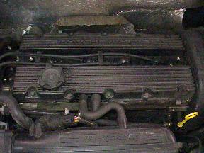
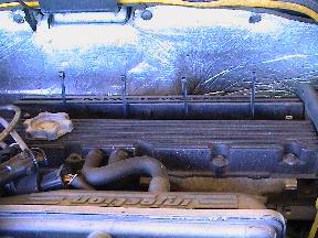
Remove the spark plug cover from the cam cover by undoing the two (captive) screws with a large cross-headed screwdriver.
- Large cross-headed screwdriver

Tools required
Carefully remove the HT plugs from the spark plugs taking care not to lose/damage either of the rubber HT lead supports.
- Blunt flat-bladed screwdriver
- Small mole grips
![]() If the HT plugs are difficult to pull out of the spark plug holes it sometimes helps to twist them slightly a few times to break the 'seal' between the rubber part of the HT plug and ceramic part of the spark plug. If the HT plugs are still stubborn then you can carefully use a flat-bladed screwdriver to lever them out. Alternatively you can pull on the top of the HT plugs carefully and gently with a pair of small mole grips.
If the HT plugs are difficult to pull out of the spark plug holes it sometimes helps to twist them slightly a few times to break the 'seal' between the rubber part of the HT plug and ceramic part of the spark plug. If the HT plugs are still stubborn then you can carefully use a flat-bladed screwdriver to lever them out. Alternatively you can pull on the top of the HT plugs carefully and gently with a pair of small mole grips.
![]() The HT leads are held in place by rubber supports across the top of the engine. Be careful when removing the HT plugs that these supports aren't lost.
The HT leads are held in place by rubber supports across the top of the engine. Be careful when removing the HT plugs that these supports aren't lost.
Tools required
Using a spark plug socket (that has a rubber insert to hold the spark plug) remove the spark plugs. If the spark plugs are going to be refitted it is a good idea to retain their positions. To do this simply write the cylinder number on the ceramic part of the spark plug with a permament pen.
- 10mm spark plug socket
- Socket handle and extension bars
- Permament pen
![]() If you have an airline available (or a can of compressed air) use it to blow any debris out of the spark plug holes before removing the spark plugs but make sure you protect your eyes.
If you have an airline available (or a can of compressed air) use it to blow any debris out of the spark plug holes before removing the spark plugs but make sure you protect your eyes.
Tools required
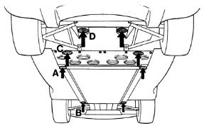
The Elise has a single jacking point each side that raises both wheels on one side at the same time. This should be
marked with a blue and white sticker with a picture of a trolley jack on it (point A in the diagram).
If the car you are working on does not have this sticker the correct jacking point is on the main
chassis rail at the point where the cockpit floor and engine undertray meet.
When raising the car use a piece of wood or similar to protect the chassis from direct contact with the saddle
of the jack.
It is preferable to have the car raised and level whilst working on it. A good way of achieving this is to use
four ramps - one under each wheel - to get the car high enough to work under.
Before raising the car, firmly apply the handbrake and chock the wheels on the opposite side to the one
you are going to raise. Carefully line up the jack up at the correct point and start to lift. Continue to raise
the car sliding the ramps under the two raised wheels as you do so (ensuring that they face opposite directions
to reduce the chance that the car will roll off) . Once you have raised it a small amount, lower the jack and
repeat on the other side. Continute raising each side in turn until all four wheels are resting on top of the
ramps.
Once the car is raised high enough to rest on top of the ramps it is a good idea to place the ramp under the front wheel with it's slope facing forwards and the ramp under the rear wheel with it's slope facing backwards. This helps to ensure the car cannot roll off the ramps and also gives better access when removing the undertray.
![]() Never work under or near a car that is only supported on a jack. Always use some additional means of
support such as ramps. Even a full box of paper under the chassis rail is sufficient.
Never work under or near a car that is only supported on a jack. Always use some additional means of
support such as ramps. Even a full box of paper under the chassis rail is sufficient.
- Suitable jack and protective pad (e.g. a piece of wood)
- Two chocks (e.g. house bricks)
- Four ramps
![]() Since there is no way of securely locating the jack on an Elise be careful about raising one side too much
higher than the other as there is a chance that the jack will slip out causing injury and damage the sill.
Since there is no way of securely locating the jack on an Elise be careful about raising one side too much
higher than the other as there is a chance that the jack will slip out causing injury and damage the sill.
![]() When placing the jack and protective pad ensure that you place it directly onto the flat surface of the
chassis rail and not onto any the fixings that are in that area.
When placing the jack and protective pad ensure that you place it directly onto the flat surface of the
chassis rail and not onto any the fixings that are in that area.
Tools required
The engine undertray is held in place by 11 8mm hex head bolts and either two
13mm hex head bolts or two 6mm cap head bolts .
There are three 8mm hex head bolts on each side just in front of the rear wheels and five
8mm hex head bolts joining the undertray to the diffuser panel.
The easiest way to remove the undertray single-handed (it is quite an unwieldy item once removed) is to remove
all 11 8mm hex head bolts and then lie under the car with your feet pointing forwards.
Loosen both the remaining bolts and then raise your feet so that they are supporting the leading (front-most)
edge of the undertray. Use one hand to take the weight of the undertray and the other to remove the remaining
bolts. Once the bolts are removed carefully pull the undertray backwards until it clears the lip at its front
edge.
Once you have the undertray resting on your body/legs, slide it either out to the side or forwards as
appropriate.
- 8mm socket
- 13mm socket
- 6mm allen key bit
- Socket handle and extension bars
![]() The undertray is likely to have debris resting on its top surface which may fall into your eyes/face
if you lower the trailing edge too much.
The undertray is likely to have debris resting on its top surface which may fall into your eyes/face
if you lower the trailing edge too much.
Tools required
The diffuser is held in place by 10 8mm hex head bolts and either two
13mm hex head bolts or two 6mm cap head bolts. There are 5 bolts joining the
diffuser to the engine undertray and 5 bolts along the back edge joining it to the rear clamshell.
Remove all the 8mm hex head bolts and then lie under the car and, whilst supporting the diffuser with
one hand, remove the remaining bolts. Once the bolts are removed carefully move the slide the diffuser out
from under the car.
- 8mm socket
- 13mm socket
- 6mm allen key bit
- Socket handle and extension bars
![]() The diffuser is likely to have debris resting on its top surface which may fall into your eyes/face
if you lower the trailing edge too much.
The diffuser is likely to have debris resting on its top surface which may fall into your eyes/face
if you lower the trailing edge too much.
Tools required
The front supports should go on the flat bottom of the main chassis rail as close as possible to the front
wheel arch. The rear supports go under the subframe where the diffuser is fixed. This is also the lower rear
wishbone rearmost mouting point.
Axle stands (with a suitable piece of protective material such as a piece of wood) are recommended for the
rear positions. Axle stands can also be used at the front (again with suitable protection against the chassis)
but anything strong and high enough will suffice. Even a full box of paper (i.e. five reams) is sufficient.
Once the car is flat on the four ramps, raise one side slightly until both wheels are clear of the ramps. Place
the supports in the correct locations and lower the car onto them. Repeat on the other side to get the car
resting on the supports and remove the ramps.
- Suitable jack and protective pad (e.g. a piece of wood)
- Axle stands and suitable protection (2)
- Support for front of car (e.g. full boxes of paper, axle stands and suitable protection) (2)
![]() Since there is no way of securely locating the jack on an Elise be careful about raising one side too much
higher than the other as there is a chance that the jack will slip out causing injury and damage the sill.
Since there is no way of securely locating the jack on an Elise be careful about raising one side too much
higher than the other as there is a chance that the jack will slip out causing injury and damage the sill.
There are four places on the Elise suitable for support. These are marked in the diagram as B (at the front)
and D (at the rear).
![]() When placing the axle stands at the rear ensure that they and the protective pads are not going to be in the
way of any work planned.
When placing the axle stands at the rear ensure that they and the protective pads are not going to be in the
way of any work planned.
Only the right-hand rear road wheel needs to be removed when replacing the cam belt.
Tools required
The S1 has 19mm hex head nuts and the S2 has 17mm hex head bolts (with the special tool).
Before undoing the road wheel nuts/bolts raise the car slightly so that some of the weight is taken on the jack. Do not raise it too far
otherwise the wheels will turn as you attempt to undo the road wheel nuts/bolts.
Place the support(s) under the correct locations and then remove the road wheel nuts/bolts (placing all the nuts/bolts/security nuts/covers in a
suitable container) and then remove the wheel from the car.
Place the removed road wheel somewhere they will not get damaged and out of the way. Also ensure that they are secure and won't fall over - i.e. don't leave them 'upright' on the tyre tread.
- 19mm socket
- Socket handle and extension bars
- Road wheel bolt special tool (S2 only - supplied with car)
- 17mm socket
- Road wheel locking nut/bolt key (supplied with car)
- Breaker bar
![]() S1 only - covering the outside of the socket you use to undo the road wheel nuts with
electrical insulation tape or similar will help prevent damage to the wheels.
S1 only - covering the outside of the socket you use to undo the road wheel nuts with
electrical insulation tape or similar will help prevent damage to the wheels.
![]() S2 only - the S2 has a special tool for the road wheel bolts. This should be included with
the tool kit car for the car.
S2 only - the S2 has a special tool for the road wheel bolts. This should be included with
the tool kit car for the car.
![]() S1 only - the locking wheel nuts have covers on them. These covers have a 'slot' across them
to distinguish them from the normal nuts. To remove the cover place the black plastic tube that the locking wheel nut key is stored in over
the cover and press firmly until it clicks on. Then remove the plastic tube and the cover should come off the nut.
S1 only - the locking wheel nuts have covers on them. These covers have a 'slot' across them
to distinguish them from the normal nuts. To remove the cover place the black plastic tube that the locking wheel nut key is stored in over
the cover and press firmly until it clicks on. Then remove the plastic tube and the cover should come off the nut.
 Loosen all four nuts/bolts just one turn in the sequence shown. Then continue to
raise the car until the tyre is clear of the ground and the car is at the desired height.
Loosen all four nuts/bolts just one turn in the sequence shown. Then continue to
raise the car until the tyre is clear of the ground and the car is at the desired height.
![]() Make sure when you loosen the road wheel locking nut/bolt the key that is firmly and squarely applied to the nut/bolt. These keys have a tendancy to 'round' if they are not properly used.
Make sure when you loosen the road wheel locking nut/bolt the key that is firmly and squarely applied to the nut/bolt. These keys have a tendancy to 'round' if they are not properly used.
![]() The wheel on S2s have a tendancy to fall off the hub/drive flange since they are not located on studs. To prevent this simply place your foot or knee gently against the bottom of the tyre before removing the road wheel bolts. Once the bolts are removed you can carefully remove the road wheel.
The wheel on S2s have a tendancy to fall off the hub/drive flange since they are not located on studs. To prevent this simply place your foot or knee gently against the bottom of the tyre before removing the road wheel bolts. Once the bolts are removed you can carefully remove the road wheel.
![]() You may find that the wheel and disc have corroded
together. This is especially common on cars with steel brake discs (as opposed to the earlier cars with MMC
brake discs). If this is the case a sharp bang on the tyre at 12 o'clock should free the wheel. Make sure if you do this that you've placed
your foot or knee against the bottom of the tyre to prevent the wheel falling off.
You may find that the wheel and disc have corroded
together. This is especially common on cars with steel brake discs (as opposed to the earlier cars with MMC
brake discs). If this is the case a sharp bang on the tyre at 12 o'clock should free the wheel. Make sure if you do this that you've placed
your foot or knee against the bottom of the tyre to prevent the wheel falling off.
Tools required
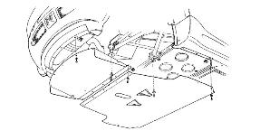
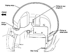
Use a cross-headed screwdriver to remove the two fixings front edge that are a plastic screw into a plastic 'plug'.
Use a cross-headed screwdriver to remove the two fixings at the back edge that are normal screws into rawlnuts.
Use a large cross-headed screwdriver to remove the screw into the rear longeron.
Finally use a 10mm hex head socket and a 10mm hex head ring spanner to undo the nut and bolt through the shear plate.
Now remove the wheelarch liner from the car.
Take care not to damage the rubber strip along the outer edge of the liner.
- Cross-headed screwdriver
- Small screwdriver flat-bladed screwdriver
- Pliers
- Small mole grips
- Blunt flat-bladed screwdriver
- Large cross-headed screwdriver
- Socket handle and extension bars
- 10mm socket
- 10mm ring spanner
![]() Sometimes these plastic screws do not undo properly. If this happens push a very small screwdriver flat-bladed screwdriver between the head of the screw and the plug and turn the screw as normal. If this does not work lever the screw out slightly and use pliers of grips to turn and pull the screw out.
Sometimes these plastic screws do not undo properly. If this happens push a very small screwdriver flat-bladed screwdriver between the head of the screw and the plug and turn the screw as normal. If this does not work lever the screw out slightly and use pliers of grips to turn and pull the screw out.
![]() Often these screws corrode into the rawlnuts causing the rawlnuts to turn in the wheelarch liner. If this happens carefully push the wheelarch liner off the rawlnut(s) with your fingers or a large flat-bladed screwdriver. Once the wheelarch liner is removed you can hold the rawlnuts with pliers or grips and undo the screw.
Often these screws corrode into the rawlnuts causing the rawlnuts to turn in the wheelarch liner. If this happens carefully push the wheelarch liner off the rawlnut(s) with your fingers or a large flat-bladed screwdriver. Once the wheelarch liner is removed you can hold the rawlnuts with pliers or grips and undo the screw.
![]() It is best to start by getting the front and rear edges of the liner over the edges of the clamshell and then the outer edge of the liner just past the edge of the clamshell. Make sure that the liner isn't fouling on the upper damper bracket and try to lift the inner part (against the longeron/shear plate) and drop the outer part.
It is best to start by getting the front and rear edges of the liner over the edges of the clamshell and then the outer edge of the liner just past the edge of the clamshell. Make sure that the liner isn't fouling on the upper damper bracket and try to lift the inner part (against the longeron/shear plate) and drop the outer part.
Tools required
The timing belt upper front cover is held in place by 6 bolts. These are all 8mm hex head bolts except the lower one which is a 10mm hex head bolt. Note that the right-hand most bolt is longer than the others.
Remove all of the 8mm hex head bolts and loosen the 10mm hex head a few turns.
Now carefully separate the upper front of the cover from the rear section.
Once the upper front cover is free from the engine slide it upwards (between the upper rear cover and clamshell) and remove it from the car.
- Socket handle and extension bars
- 8mm socket
- 10mm socket
![]() There is a moulded rubber seal between the engine mount and the upper front cover. Take care not to damage this when removing the upper front cover.
There is a moulded rubber seal between the engine mount and the upper front cover. Take care not to damage this when removing the upper front cover.
![]() Although it will seem that there is no room to remove the upper front cover with patience it will fit. Take care not to damage the upper front cover or upper rear cover.
Although it will seem that there is no room to remove the upper front cover with patience it will fit. Take care not to damage the upper front cover or upper rear cover.
Tools required
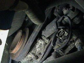
Using a 15mm hex head socket loosen the alternator pivot and clamp bolts (labelled 'A' and 'B' respectively in the diagram). There is no need to completely remove the nuts - just undo them a few turns to allow the alternator to move freely.
- Socket handle and extension bars
- 15mm socket
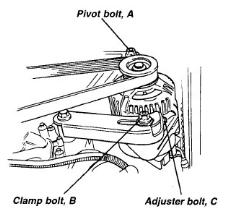
![]() Note that even with the pivot and clamp bolts loosened the alternator will not move. This is because it is held in place by the adjuster bolt (labeled 'C' in the diagram).
Note that even with the pivot and clamp bolts loosened the alternator will not move. This is because it is held in place by the adjuster bolt (labeled 'C' in the diagram).
Tools required
Using a 8mm hex head socket loosen the alternator adjuster bolt (labelled 'C' in the diagram).
- Socket handle and extension bars
- 8mm socket
- Wire cutters
![]() To allow the alternator to move towards the engine you will need to undo (turn anti-clockwise) the adjuster bolt.
To allow the alternator to move towards the engine you will need to undo (turn anti-clockwise) the adjuster bolt.
![]() You may find that alternator body fouls on a cable tie holding part of the wiring loom to the lower alternator bracket. If this is the case simply cut it using wire cutters to allow the alternator to move freely.
You may find that alternator body fouls on a cable tie holding part of the wiring loom to the lower alternator bracket. If this is the case simply cut it using wire cutters to allow the alternator to move freely.
To remove the alternator drive belt simply push the (loosened) alternator towards the engine and lift the belt off the alternator pulley. Once it is off the alternator pulley lift it off the crankshaft pulley and withdraw it from the car.
Tools required
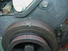
Insert a large flat-bladed screwdriver into the flywheel ring gear where a small section is visible next to the right-hand driveshaft.
The crankshaft pulley is on the left-hand side in the photograph. The pulley bolt is a 22mm hex head.
Using a suitable breaker bar (or an alternative such as a piece of scaffolding pole) loosen the crankshaft pulley bolt.
![]() The crankshaft pulley bolt is a very high torque bolt. Take great care when attempting to loosen it.
The crankshaft pulley bolt is a very high torque bolt. Take great care when attempting to loosen it.
- Socket handle and extension bars
- 22mm socket (short)
- Breaker bar
- Large flat-bladed screwdriver
![]() Make sure that the screwdriver/tool you insert into the ring gear is of the correct size, shape and material to hold the flywheel/crankshaft as you loosen the crankshaft pulley bolt as this bolt is very high torque.
Make sure that the screwdriver/tool you insert into the ring gear is of the correct size, shape and material to hold the flywheel/crankshaft as you loosen the crankshaft pulley bolt as this bolt is very high torque.
![]() Unfortunately there is little clearance between the crankshaft pulley and the chassis so you will need to cut down a 22mm hex head socket to be ????????? deep.
Unfortunately there is little clearance between the crankshaft pulley and the chassis so you will need to cut down a 22mm hex head socket to be ????????? deep.
![]() Do not be tempted to 'bang' or 'yank' the breaker bar - this may cause the screwdriver holding the flywheel ring gear to become dislodged which may in turn lead to injury and/or damage to the ring gear. Apply steady pressure to the breaker bar until the crankshaft pulley bolt is loose.
Do not be tempted to 'bang' or 'yank' the breaker bar - this may cause the screwdriver holding the flywheel ring gear to become dislodged which may in turn lead to injury and/or damage to the ring gear. Apply steady pressure to the breaker bar until the crankshaft pulley bolt is loose.
Tools required
Materials required
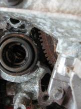
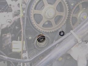
Rotate the engine clockwise using a 22mm hex head socket on the crankshaft pulley bolt until the 'IN' and 'EXHAUST' markings on the camshaft pulleys line up. This places the engine at 90° BTDC.
To double-check that the engine is at 90° BTDC ensure the notch crankshaft pulley is aligned with the mark on the timing belt lower cover.
Insert the camshaft pulley locking tool between the camshaft pulleys.
As an additional check for 90° BTDC carefully insert 4 cable ties into the spark plug holes. If the engine is at 90° BTDC the cable ties will all be at the same level.
- Socket handle and extension bars
- 22mm socket (short)
- Camshaft pulley locking tool
- Cable ties
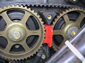
![]() The camshaft pulleys can be aligned 180° from the photograph - this does not matter. The engine will still be at 90° BTDC since the camshafts turn one revolution for every two crankshaft revolutions. As long as the marks on the camshaft pulleys are aligned the engine position is correct.
The camshaft pulleys can be aligned 180° from the photograph - this does not matter. The engine will still be at 90° BTDC since the camshafts turn one revolution for every two crankshaft revolutions. As long as the marks on the camshaft pulleys are aligned the engine position is correct.
![]() You may need to rotate the engine very slightly to allow the camshaft pulley locking tool to be inserted.
You may need to rotate the engine very slightly to allow the camshaft pulley locking tool to be inserted.
Tools required
Use a cut-down 22mm hex head socket to undo the crankshaft pulley bolt. Once it is loosened it should be possible to undo the bolt by hand which will be easier as there is very limited access for tools between the crankshaft pulley and the chassis.
- Socket handle and extension bars
- 22mm socket (short)
![]() Some cars have threadlock applied to the crankshaft pulley bolt. If this is the case you may need to use a socket/spanner to remove the crankshaft pulley bolt.
Some cars have threadlock applied to the crankshaft pulley bolt. If this is the case you may need to use a socket/spanner to remove the crankshaft pulley bolt.
Tools required
TIMING BELT LOWER COVER PHOTO
The timing belt lower cover is held in place by 4 bolts. These are all 8mm hex head bolts.
Remove all of the 8mm hex head bolts.
Now carefully separate the lower of the cover from the engine
- Socket handle and extension bars
- 8mm socket
![]() There is a moulded rubber seal between the engine mount and the lower cover. Take care not to damage this when removing the lower cover.
There is a moulded rubber seal between the engine mount and the lower cover. Take care not to damage this when removing the lower cover.
Tools required
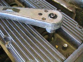
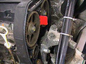
The 2 manual tensioner bolts are highlighted in the photograph.
Remove the 8mm hex head and then loosen the 8mm cap head.
Once the 8mm cap head is loosened push the tensioner down as far as possible and do up the main tensioner bolt finger tight. This will hold the tensioner out of the way of the timing belt.
- Socket handle and extension bars
- 8mm socket
- 8mm allen key bit
![]() Often the tensioner main bolt is extremely tight so take precautions when undoing it to avoid injury.
Often the tensioner main bolt is extremely tight so take precautions when undoing it to avoid injury.
Tools required
Place a jack (with a piece of wood or similar for protection) under the sump and put the jack/wood/protection gently into contact with the sump so that it just starts to lift the engine.
Use a 18mm hex head socket to undo and remove the two engine mount bolts.
Once both bolts are removed jack the engine up to give approximately 3cm clearance between the chassis part of the engine mount and the engine part of the engine mount.
- Suitable jack and protective pad (e.g. a piece of wood)
- Socket handle and extension bars
- Breaker bar
- 18mm socket
Carefully withdraw the cam belt from the camshaft pulleys, tensioner, water pump and crankshaft pulley.
Once the belt has been removed from the pulleys/tensioner/water pump remove it from the car by carefully sliding it through the gap in the right-hand engine mount.
![]() When handling a cam belt always ensure that your hands are free from oil/grease/dirt and that the belt is not kinked or twisted.
When handling a cam belt always ensure that your hands are free from oil/grease/dirt and that the belt is not kinked or twisted.
![]() It is normally easier to pull the timing belt off each item a little at a time as the belt has vey little 'give' in it.
It is normally easier to pull the timing belt off each item a little at a time as the belt has vey little 'give' in it.
Tools required
Remove both the manual tensioner bolts (highlighted in the photograph) and remove the cam belt tensioner from the car.
- 8mm socket
- Socket handle and extension bars
- 8mm allen key bit
Tools required
Materials required
Place the cam belt tensioner in position and insert the larger of the two bolts (8mm cap head) a few turns to hold the tensioner in place.
Now fit the smaller of the two bolts (8mm hex head) a few turns.
Push the tensioner down as far as possible and do up both bolts finger tight. This will hold the tensioner out of the way of the timing belt.
- Socket handle and extension bars
- 8mm socket
- 8mm allen key bit
- New manual cam belt tensioner
Materials required
If required thoroughly clean the engine mount to prevent the cam belt picking up any dirt as it is fitted.
Working from below carefully place the cam belt over the engine part of the right-hand engine mount. Working from inside the wheelarch lift the belt so that it just rests on the camshaft pulleys.
With one hand hold the cam belt just on the edge (not the whole width of the belt) of the crankshaft pulley and with the other pull the cam belt taut along the upwards run on the right-hand side and engage just the edge (not the whole width of the belt) with the exhaust camshaft pulley.
Ensuring that the belt does not slip from the crankshaft or exhaust camshaft pulley pull the belt taut along the top horizontal run and engage just the edge (not the whole width of the belt) with the inlet camshaft pulley.
Ensuring that belt does not slip from the crankshaft or camshaft pulleys, engage just the edge (not the whole width of the belt) with the tensioner and finally the water pump (which may need to be rotated slighly to align the teeth and the belt).
The cam belt should now be fitted over the crankshaft pulley, both camshaft pulleys, the tensioner and the water pump.
Gently and carefully push the cam belt onto the pulleys, tensioner and water pump moving it a small amount at a time and working round in a circle. Repeat until the cam belt is in the middle of the pulleys, tensioner and water pump.
- Rag/cloth/tissue
- New cam belt
![]() When handling a cam belt always ensure that your hands are free from oil/grease/dirt and that the belt is not kinked or twisted.
When handling a cam belt always ensure that your hands are free from oil/grease/dirt and that the belt is not kinked or twisted.
Tools required
Torque settings
Loosen both tensioner bolts a few turns to allow the tensioner to move freely.
Push the tensioner upwards until it is in the same position as the one that was removed.
Hold the tensioner in this position and tighten both bolts finger tight.
Tighten the main 8mm cap head to 45Nm and the smaller 8mm hex head to 10Nm.
- Socket handle and extension bars
- 8mm socket
- 8mm allen key bit
- Torque wrench
- Large flat-bladed screwdriver
- Manual cam belt tensioner main bolt (K series) 45Nm
- Manual cam belt tensioner adjustment bolt (K series) 10Nm
![]() It is often easier to hold the tensioner in place with a screwdriver while tightening the bolts.
It is often easier to hold the tensioner in place with a screwdriver while tightening the bolts.
Tools required
Torque settings
Fit the timing belt lower cover aligning the holes in it with those in the engine.
Replace all 4 8mm hex head bolts a few turns at first and then tighten them all to 9Nm
- Socket handle and extension bars
- 8mm socket
- Timing belt lower cover bolt (K series) 9Nm
![]() There is a moulded rubber seal between the engine mount and the lower cover. Take care this in place and not damaged when fitting the lower cover.
There is a moulded rubber seal between the engine mount and the lower cover. Take care this in place and not damaged when fitting the lower cover.
Tools required
Materials required
Ensure the inner face of the crankshaft pulley, washer and thread of the crankshaft pulley bolt are clean.
Fit the crankshaft pulley onto the end of the crankshaft and tighten the bolt finger tight.
At this stage there is no need to tighten the bolt fully - just enough to hold the crankshaft pulley firmly in place.
- Socket handle and extension bars
- 22mm socket (short)
- Wire brush
- Rag/cloth/tissue
![]() The crankshaft pulley has a notch in it that locates it onto the crankshaft. Ensure that the crankshaft pulley is correctly seated before tightening the bolt.
The crankshaft pulley has a notch in it that locates it onto the crankshaft. Ensure that the crankshaft pulley is correctly seated before tightening the bolt.
Tools required
Rotate the engine clockwise using a 22mm hex head socked on the crankshaft pulley bolt. Continue turning the engine so that the crankshaft goes through 2 complete revolutions and the camshaft go through 1 complete revolution.
After 2 complete crankshaft revolutions line up the camshaft pulley timing marks ('IN' and 'EXHAUST' markings lined in).
Check that the crankshaft pulley notch is aligned with the timing mark on the timing belt lower cover.
- Socket handle and extension bars
- 22mm socket (short)
![]() If the camshaft pulley locking tool is still inserted remove it.
If the camshaft pulley locking tool is still inserted remove it.
Tools required
Torque settings
Insert a large flat-bladed screwdriver into the flywheel ring gear where a small section is visible next to the right-hand driveshaft.
Tighten the crankshaft pulley bolt to 205Nm.
![]() The crankshaft pulley bolt is a very high torque bolt. Take great care when attempting to tighten it.
The crankshaft pulley bolt is a very high torque bolt. Take great care when attempting to tighten it.
- Socket handle and extension bars
- 22mm socket (short)
- Torque wrench
- Large flat-bladed screwdriver
- Crankshaft pulley bolt (K series) 205Nm
![]() Make sure that the screwdriver/tool you insert into the ring gear is of the correct size, shape and material to hold the flywheel/crankshaft as you loosen the crankshaft pulley bolt as this bolt is very high torque.
Make sure that the screwdriver/tool you insert into the ring gear is of the correct size, shape and material to hold the flywheel/crankshaft as you loosen the crankshaft pulley bolt as this bolt is very high torque.
Tools required
Materials required
Torque settings
Thoroughly clean the threads of both the right-hand engine mount bolts to remove any old threadlock, corrosion etc.
Raise the engine using the jack that is supporting it until there is around 5mm clearance between the chassis part of the engine mount and the engine part of the engine mount.
Insert one bolt through the chassis part of the engine mount and do it up into the engine part of the engine mount.
Once the bolt has 'found' the thread continue tightening it until it just touches the top of the chassis part of the engine mount (ensuring there is still some clearance between the two parts of the engine mount).
Apply Permabond or similar to the other bolt and insert it into the engine mount.
Once the head of the second bolt touches the chassis part of the engine mount remove the first bolt, clean the threads, apply some Permabond or similar and insert it again so that both bolt heads are touching the engine mount.
Raise the engine so that it touches and just starts to lift the chassis part of the engine mount.
Tighten both bolts to 82Nm.
- Socket handle and extension bars
- 18mm socket
- Torque wrench
- Wire brush
- Permabond
- Right-hand engine mount bolt (K series) 82Nm
![]() To allow the bolt to 'find' the thread in the engine mount you may need to move the engine backwards or forwards.
To allow the bolt to 'find' the thread in the engine mount you may need to move the engine backwards or forwards.
Materials required
Place the alternator drivebelt over the crankshaft pulley and, whilst pushing the alternator towards the engine, slip the belt over the alternator pulley.
Check the belt is correctly seated on both pulleys.
- New alternator drivebelt (K series)
Tools required
Using a 8mm hex head socket tighten the alternator adjuster bolt (labelled 'C' in the diagram).
Continue tightening the adjust bolt until the lower alternator clamp bolt is lined up with the mark of it's previous position.
- Socket handle and extension bars
- 8mm socket
![]() To tighten the alternator drivebelt you will need to do up (turn clockwise) the adjuster bolt.
To tighten the alternator drivebelt you will need to do up (turn clockwise) the adjuster bolt.
Tools required
Materials required
Torque settings
Using a 15mm hex head socket tighten the alternator pivot and clamp bolts (labelled 'A' and 'B' respectively in the diagram) to 30Nm.
- Socket handle and extension bars
- 15mm socket
- Wire cutters
- Cable ties
- Alternator pivot and clamp bolts 30Nm
![]() If you had to cut a cable tie holding part of the wiring loom to the lower alternator bracket replace it now.
If you had to cut a cable tie holding part of the wiring loom to the lower alternator bracket replace it now.
Tools required
Place the negative battery clamp onto the negative battery post and tighten the clamp nut using a 13mm hex head open-ended spanner.
![]() Always take great care when using metal tools near the battery terminals as it is possible to short-circuit the battery.
Always take great care when using metal tools near the battery terminals as it is possible to short-circuit the battery.
- 13mm open-ended spanner
![]() The negative terminal is the one nearest the centre of the car with the black cables running to it.
The negative terminal is the one nearest the centre of the car with the black cables running to it.
![]() Do not overtighten the battery clamp bolt. Ensure that the clamp is firmly held on the battery post but there is no need to do the clamp bolt up very tight.
Do not overtighten the battery clamp bolt. Ensure that the clamp is firmly held on the battery post but there is no need to do the clamp bolt up very tight.
![]() When placing the battery clamp onto the battery post there is usually a beep from the alarm system. This is normal.
When placing the battery clamp onto the battery post there is usually a beep from the alarm system. This is normal.
Tools required
Materials required
Torque settings
Use a spark plug socket to place all the spark plugs into the cylinder head and tighten them to finger tight.
Tighten all the spark plugs to 25Nm.
- Socket handle and extension bars
- 10mm spark plug socket
- Torque wrench
- Oil (for spark plug threads)
- Spark plug (K series) 25Nm
![]() It is best to just use a spark plug socket and extension bar (if necessary) to get the spark plugs started in their threads. If any kind of tool (like a socket handle) is used there is a chance the spark plug will become cross-threaded.
It is best to just use a spark plug socket and extension bar (if necessary) to get the spark plugs started in their threads. If any kind of tool (like a socket handle) is used there is a chance the spark plug will become cross-threaded.
Replace the HT plugs onto the spark plugs ensuring that the rubber supports are in place and that the leads do not rub against each other, the HT plugs, the cam cover or any bolt heads.
![]() There should be a 'click' when the HT plug is correctly seated onto the spark plug.
There should be a 'click' when the HT plug is correctly seated onto the spark plug.
Ensure the handbrake is firmly applied and that the gearbox is in neutral start the engine in the normal way.
The engine should start and idle normally and respond to gentle throttle inputs.
![]() Be careful not to get any tools/clothing/etc. tangled in the cam belt or camshaft pulleys as these are exposed.
Be careful not to get any tools/clothing/etc. tangled in the cam belt or camshaft pulleys as these are exposed.
Tools required
Torque settings
Insert the timing belt upper front cover from above between the upper rear cover and the clamshell.
Place the upper front cover in place over the rear cover and replace the 5 8mm hex head bolts and tighten the 10mm hex head bolt to 5Nm.
- Socket handle and extension bars
- 8mm socket
- 10mm socket
- Timing belt upper front cover bolt (K series) 5Nm
![]() There is a moulded rubber seal between the engine mount and the upper front cover. Take care not to damage it when fitting the upper front cover.
There is a moulded rubber seal between the engine mount and the upper front cover. Take care not to damage it when fitting the upper front cover.
![]() Ensure the rubber seal is correctly seated between the engine mount and the upper front cover before fully tightening the bolts.
Ensure the rubber seal is correctly seated between the engine mount and the upper front cover before fully tightening the bolts.
Tools required
Materials required
Replace the wheelarch liner into the wheelarch taking care not to damage the rubber strip along the outer edge.
Put a smear of copper grease on the threads of all screws/bolts and replace them in their respective positions.
- Cross-headed screwdriver
- Socket handle and extension bars
- 10mm socket
- 10mm ring spanner
- Copper grease
![]() The wheelarch liners do not need to be over-tightened - just finger tight and then nipped up is sufficient.
The wheelarch liners do not need to be over-tightened - just finger tight and then nipped up is sufficient.
Tools required
Materials required
The S1 has 19mm hex head nuts and the S2 has 17mm hex head bolts (with the special tool).
Put a thin smear of copper grease or similar on the outer face of the brake disc where it comes into contact with the road wheel. This will
help prevent the two corroding together. Also put a thin smear of copper grease on the road wheel studs/wheel bolts.
Carefully lift the road wheel into position. On an S1 this will mean placing the road wheel over the studs on the hub/drive flange. On an S2 you need
to make sure that the bolt holes in the wheel line up with the bolt holes in the disc.
Hold the wheel in place by placing your foot or knee gently against the bottom of the tyre and put the nuts/bolts back. At this stage just finger-tight is
sufficient.
Once all four nuts/bolts are in place and finger-tight use a socket handle to just nip them up a little bit more. Don't overtighten them but make sure the wheel isn't loose.
- 19mm socket
- 17mm socket
- Socket handle and extension bars
- Road wheel bolt special tool (S2 only - supplied with car)
- Road wheel locking nut/bolt key (supplied with car)
- Copper grease
- Rag/cloth/tissue
![]() It is worth putting a little copper grease or similar on the road wheel studs/bolts as it will help with
subsequent removal.
It is worth putting a little copper grease or similar on the road wheel studs/bolts as it will help with
subsequent removal.
![]() S1 only - covering the outside of the socket you use to tighten the road wheel nuts with
electrical insulation tape or similar will help prevent damage to the wheels.
S1 only - covering the outside of the socket you use to tighten the road wheel nuts with
electrical insulation tape or similar will help prevent damage to the wheels.
![]() S2 only - the S2 has a special tool for the road wheel bolts. This should be included with
the tool kit car for the car.
S2 only - the S2 has a special tool for the road wheel bolts. This should be included with
the tool kit car for the car.
Tools required
Removing the axle stands from under the car is the reverse of putting them there - locate the jack/protective pad at the correct point and
raise the car clear of the axle stands/supports.
Place ramps under both wheels on the side that is raised and remove the axle stands/supports.
Carefully lower the car until it is resting on the ramps.
Repeat for the other side.
- Suitable jack and protective pad (e.g. a piece of wood)
- Four ramps
![]() Since there is no way of securely locating the jack on an Elise be careful about raising one side too much
higher than the other as there is a chance that the jack will slip out causing injury and damage the sill.
Since there is no way of securely locating the jack on an Elise be careful about raising one side too much
higher than the other as there is a chance that the jack will slip out causing injury and damage the sill.
Tools required
Materials required
To refit the diffuser panel lie under the car ensuring that you have the
two 13mm hex head bolts or 6mm cap head
bolts easily to hand.
Raise the diffuser panel into position and insert the two 'main' bolts but do not completely tighten them at this stage.
Replace the remaining 10 8mm hex head bolts but again do not completely tighten them as you
may well need to move the diffuser panel slightly to get some of the bolts in.
Once all the bolts are in, lie under the car and pushing the diffuser panel upwards with
one hand fully tighten the two 'main' bolts. Now fully tighten the five bolts joining the diffuser panel to the
rear clam and then fully tighten the five bolts joining the diffuser panel to the engine undertray.
- 8mm socket
- 13mm socket
- 6mm allen key bit
- Socket handle and extension bars
- Copper grease
- Rag/cloth/tissue
![]() It is worth putting a little copper grease or similar on all the diffuser panel bolts before refitting them as it will help with
subsequent removal.
It is worth putting a little copper grease or similar on all the diffuser panel bolts before refitting them as it will help with
subsequent removal.
![]() Be careful when tightening the 8mm hex head bolts
as they are only held in place by spire nuts. As long as the diffuser panel is held firmly that is sufficient.
Be careful when tightening the 8mm hex head bolts
as they are only held in place by spire nuts. As long as the diffuser panel is held firmly that is sufficient.
Tools required
Materials required
To refit the engine undertray lie under the car with your feet pointing forwards ensuring that you have the
two 13mm hex head bolts or 6mm cap head
bolts easily to hand.
Slide the undertray onto your body/legs and using your feet raise the leading (front-most) edge and push it
forwards into its 'slot' at the rear of the cockpit floor. Now insert the two 'main' bolts but do not completely
tighten them at this stage.
Replace the remaining 11 8mm hex head bolts but again do not completely tighten them as you
may well need to move the undertray slightly to get some of the bolts in.
Once all the bolts are in, lie under the car again and pushing the undertray forward into its 'slot' with
one hand fully tighten the two 'main' bolts. Now fully tighten the five bolts joining the undertray to the
diffuser and then fully tighten the three bolts on each side.
- 8mm socket
- 13mm socket
- 6mm allen key bit
- Socket handle and extension bars
- Copper grease
- Rag/cloth/tissue
![]() It is worth putting a little copper grease or similar on all the undertray bolts before refitting them as it will help with
subsequent removal.
It is worth putting a little copper grease or similar on all the undertray bolts before refitting them as it will help with
subsequent removal.
![]() Be careful when tightening the 8mm hex head bolts as they are only held in place by spire
nuts. As long as the undertray is held firmly that is sufficient.
Be careful when tightening the 8mm hex head bolts as they are only held in place by spire
nuts. As long as the undertray is held firmly that is sufficient.
Tools required
Lowering the car is the reverse of raising it - locate the jack/protective pad at the correct point and
raise the car clear of the ramps. Slide the ramps out slightly and carefully lower the car. Now lower
the jack and repeat on the other side. Continue lowering each side in turn until the car is resting on
the floor.
- Suitable jack and protective pad (e.g. a piece of wood)
- Two chocks (e.g. house bricks)
- Four ramps
Tools required
Materials required
Before fitting the spark plug cover put a thin smear of copper grease on the captive screws.
Place the spark plug cover in place on top of the engine and tighten the two screws.
- Large cross-headed screwdriver
- Copper grease
![]() The spark plug cover screws do not need to be over-tightened - just finger tight and then nipped up is sufficient.
The spark plug cover screws do not need to be over-tightened - just finger tight and then nipped up is sufficient.
Fit the screenwash reservoir onto it's bracket by sliding it straight down.
Connnect the electrical connection to the screenwash pump by carefully connecting the plug onto the pump.
![]() Whenever the screenwash pump electrical connection is disturbed it is always a good idea to test that the pump still works before driving the car.
Whenever the screenwash pump electrical connection is disturbed it is always a good idea to test that the pump still works before driving the car.